For my solar water heating information pages click here.
For my electrical consumption monitoring project click here.
For some reviews of products click here.
BackgroundThe system is located in Martlesham in Suffolk. It is a village location in a rural area just outside Ipswich. This page provides some general information about my home weather monitoring project. The actual weather readings and plots for the past 24 hours and 28 days can be viewed on the data page I also upload my data to Weather Underground and my station can be viewed by clicking on the banner below. |
View Larger Map |
How it works
My system currently measures temperature, relative humidity/dewpoint, rainfall and pressure. The notes below describe how I built up the system (starting in early 2007) which is fully automated and logs readings every 15 minutes and records them on my web site and on Weather Underground.
I have three temperature sensors, which are on the outside of my house and positioned to be in shade but with reasonable air flow. I initially had two sensors but was tending to get slightly high readings when it was sunny. From 28th June 2007 I have included a new third sensor and the system takes the valid reading as the lowest of the three to minimise any local heating effects and this seems to have resolved the problems I had initially. As of 19th August 2007 I added a rain gauge so the data page now shows the rate in mm per 15 minute interval.
The sensors operate over a 1-wire bus and the temperature sensors are made using DS18S20 sensors which can be acquired from Quasar Electronics. My mini-ITX server running Linux takes measurements every 15 minutes and logs the results as well as posting the latest values to this site. Below are some pictures and explanation of how I built the system up.
I recently constructed an uninterruptable power supply to keep the mini-ITX up and running even if the mains fails. I've described this, along with some pictures, on a separate page.
I must give some credit also to Jonathan Hudson who developed some excellent software to run the 1-wire interface and take the readings. His excellent site describes what you need to do if you are keen to set up a similar system.
Sunrise and sunset details
This week (3rd December 2008) I've been working on adding sunrise and sunset values to the weather data page. It turned out to be pretty simple as I just needed to set up a daily batch job to fetch the details from the really useful EarthTools web site using one of their web services and then push the values to my web site.
Humidity sensor
 During August 2008 I've added a relative humidity sensor. I built this up from a Hobby Boards kit. I enclosed it in a small box from Maplin (once I'd drilled plenty of ventilation holes).
It uses the Honeywell HIH-4000 device and Jonathan Hudson's recent versions of w1retap support it so once I'd upgraded my software it was up
and running with no apparent problems.
During August 2008 I've added a relative humidity sensor. I built this up from a Hobby Boards kit. I enclosed it in a small box from Maplin (once I'd drilled plenty of ventilation holes).
It uses the Honeywell HIH-4000 device and Jonathan Hudson's recent versions of w1retap support it so once I'd upgraded my software it was up
and running with no apparent problems.
 I've included code in my script to calculate the dew point using a formula from the NPL web site
(described in their FAQ section).
This is now shown as a green line on my temperature graph.
I've included code in my script to calculate the dew point using a formula from the NPL web site
(described in their FAQ section).
This is now shown as a green line on my temperature graph.
Pressure sensor
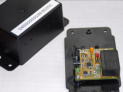 A recent mini-project has been to build a barometric pressure sensor. This was based on Andrew Miller's enhanced version of the
"Bray" design. I'm grateful to Mihail who supplied me with a spare PCB which allowed me to build it up. It meant learning how to solder surface mount components by hand
but once I got used to that it went really well and worked first time.
A recent mini-project has been to build a barometric pressure sensor. This was based on Andrew Miller's enhanced version of the
"Bray" design. I'm grateful to Mihail who supplied me with a spare PCB which allowed me to build it up. It meant learning how to solder surface mount components by hand
but once I got used to that it went really well and worked first time.
 I ran it initially for a couple of weeks to calibrate it against readings from local stations
and it looked extremely close (although I had to apply a fixed offset to bring it into line). Since November 2007 the readings have been posted regularly on the website along with the other sensors.
I ran it initially for a couple of weeks to calibrate it against readings from local stations
and it looked extremely close (although I had to apply a fixed offset to bring it into line). Since November 2007 the readings have been posted regularly on the website along with the other sensors.
 I also designed and built a voltage upconverter (needed to drive the 10v regulator in the pressure sensor circuit) so that I could power the sensor
using the 5v supply from the USB 1-wire adapter. The upconverter was based on an
LT1109A and set up to produce around 13.5v which I feed down the CAT5 cable in a separate pair.
I also designed and built a voltage upconverter (needed to drive the 10v regulator in the pressure sensor circuit) so that I could power the sensor
using the 5v supply from the USB 1-wire adapter. The upconverter was based on an
LT1109A and set up to produce around 13.5v which I feed down the CAT5 cable in a separate pair.
 Care is needed with this as it can affect performance of the bus and some experimentation was needed in order to get this going properly. The overall network
configuration is now something like this.
Care is needed with this as it can affect performance of the bus and some experimentation was needed in order to get this going properly. The overall network
configuration is now something like this.
Rainfall sensor
 I purchased a rainfall sensor from Hobby Boards. It took me a little while to build the platform for this
but it is now installed and running.
The platform was assembled in two parts using exterior grade ply - construction
technique shown for one of the pieces in the photo - and then given a weatherproof coating.
I purchased a rainfall sensor from Hobby Boards. It took me a little while to build the platform for this
but it is now installed and running.
The platform was assembled in two parts using exterior grade ply - construction
technique shown for one of the pieces in the photo - and then given a weatherproof coating.
 The sensor sits slightly above the roof level on the end of the house. The picture also shows the special
"bird protector" around the rim of the gauge which I made using short pieces of glass fibre rod - 100mm long - and attached using a length of
small diameter hose.
The sensor sits slightly above the roof level on the end of the house. The picture also shows the special
"bird protector" around the rim of the gauge which I made using short pieces of glass fibre rod - 100mm long - and attached using a length of
small diameter hose.
 I'm hoping this will discourage perching which I've heard can be a problem with rain gauges.
Temperature sensor construction and wiring
 The basic components needed for the temperature sensor are the DS18S20 along with the 1N5817 diode (optional but improves noise immunity on long cable runs).
 The aim is to wire the sensor as shown in the circuit diagram so wrap pin 3 of the DS18S20 round the
  back until it touches pin 1 but take care not to short it to pin 2. Solder it where it touches then trim to length. Next bend the diode so that you can
connect the end with the stripe to pin 2 and other end to pin 1. Carefully solder it in place bearing in mind you are going to need to fit it inside the
plastic tubing. Trim the excess from the diode terminals. Also make sure you keep the devices well heat-sinked while doing the soldering with
something like pliers so that they don't get any heat damage.
back until it touches pin 1 but take care not to short it to pin 2. Solder it where it touches then trim to length. Next bend the diode so that you can
connect the end with the stripe to pin 2 and other end to pin 1. Carefully solder it in place bearing in mind you are going to need to fit it inside the
plastic tubing. Trim the excess from the diode terminals. Also make sure you keep the devices well heat-sinked while doing the soldering with
something like pliers so that they don't get any heat damage.

 Cut a length of plastic tubing approx 6mm internal diameter and 300-400mm long. DIY chains usually stock this at quite reasonable prices.
 Prepare the telephone flex (up to around 500mm) by trimming the covering and stripping the ends of the two centre wires. Thread it through
the tubing so that enough of it is exposed at the end.
Prepare the telephone flex (up to around 500mm) by trimming the covering and stripping the ends of the two centre wires. Thread it through
the tubing so that enough of it is exposed at the end.
 Solder the wires to the pins from the DS18S20 - pin 2 (data, normally white but depends on the flex you have bought) and pin 1 (gnd).
Once you are sure the connections are correct, mix up some epoxy resin and coat the exposed pins and wires. Use just enough for a little protection
and insulation at this stage as there needs to be room to fit into the tube later.
Solder the wires to the pins from the DS18S20 - pin 2 (data, normally white but depends on the flex you have bought) and pin 1 (gnd).
Once you are sure the connections are correct, mix up some epoxy resin and coat the exposed pins and wires. Use just enough for a little protection
and insulation at this stage as there needs to be room to fit into the tube later.Leave time for the epoxy to set.
 Once the first lot of epoxy has set then mix up a little more and coat the wires again and carefully slide the wiring inside the tube.
Leave the sensor itself poking out of the end and just let the epoxy fill the end of the tube and touch the bottom edge of the sensor body.
Once the first lot of epoxy has set then mix up a little more and coat the wires again and carefully slide the wiring inside the tube.
Leave the sensor itself poking out of the end and just let the epoxy fill the end of the tube and touch the bottom edge of the sensor body.
Leave this to set properly.
 Prepare the connection box and run the flex from the sensor into the back of the surface box. The RJ11 sockets are insulation-displacement so it's best to solder short lengths
of single core wire (e.g. out of some spare CAT5E cable) to the ends of the data/gnd wires from the telephone flex and use this to push into the back of the sockets.
Prepare the connection box and run the flex from the sensor into the back of the surface box. The RJ11 sockets are insulation-displacement so it's best to solder short lengths
of single core wire (e.g. out of some spare CAT5E cable) to the ends of the data/gnd wires from the telephone flex and use this to push into the back of the sockets.
 Connect to pins 3 (data) and 4 (gnd) on the RJ11 sockets and link both sockets together in the same box so that the 1-wire bus is daisy-chained.
You can make up lengths of RJ11 to RJ11 and RJ11 to RJ45 as appropriate. I think my cable run overall is around 10m through the CAT5E and another 15-20m through telephone flex and performance is pretty solid.
 I used the wiring convention shown here
 and this matches up with the connections into the USB adapter (DS2490).

 Installing the sensors involves drilling a hole through the wall with the connection box on the inside and the tube pushed through so
that the sensor just comes out into the fresh air. This is one of the finished installed sensors with a little shield I made up to protect it whilst
still allowing good air flow.
Installing the sensors involves drilling a hole through the wall with the connection box on the inside and the tube pushed through so
that the sensor just comes out into the fresh air. This is one of the finished installed sensors with a little shield I made up to protect it whilst
still allowing good air flow.